Pages

Sunday, November 20, 2005

Speedbrake position sensor


The GRT EFIS has the ability to display trim & flap positions based on the use of Ray Allen position sensors or trim servos. The Ray Allen is a linear POT that varies resistance with position. I wanted to install one on our speedbrake so that we can see the position of it on the EFIS screen. I am hoping that GRT adds a Speedbrake label to the indicator (I requested the feature) and that they also add extension warnings based on speed/RPM, etc... The above photo shows the Pitch Trim indicator and the Speedbrake indicator (Labeled as flaps). This was the last photo I took after I got it working. The roll trim servo is not yet mounted to the airframe.

I started with the sensor taped up to a mounting block, along with some Dubro linkage. The Dubro linkage is designed for RC aircraft use, is very durable, lightweight and is sold at hobby stores. Some 4-40 allthread is used for the shaft. I ended up mounting the sensor directly to the seat back with two nut plates.

This photo shows the linkage attached to the speedbrake. I created a bracket from some aluminum angle and bolted it under one of the hinge attach bolts. Of course this project ended up taking the entire work day even though I was sure it was only about 2 hours of work. But fabricating the linkage, mounting bracket, installing nut plates, wiring, adjusting, calibrating and testing took longer that I figured. At least I didn't have to mix any epoxy! I'll be back to fiberglass work on Tuesday.

Friday, November 18, 2005

A little bit of everything


So I started today with... guess what... more fiberglass work. I have learned that I dislike fiberglass work enough to realize that building one from scratch just isn't my cup of tea. I'm glad this one is pretty close to done.

Once I had all the fiberglass work I could stand (which wasn't much) I decided to find something else to do. I got out the Infinity stick grip for the back seat that still needed to have a molex connector installed. This is a good hour worth of work stripping all 15 wires on both ends, crimping on 30 pins and building up the connectors. I wired it to match the front stick so either stick can plug in and work the same. Note that I used a 15 conductor plug instead of the 16 conductor that is specified by Infinity Aerospace. I combined the ground wire on two of the switches that send signals to ground to eliminate one wire. I couldn't find a good 16 pin connector, but 15 pin seemed to be plentiful.

I've got the pitot tube hardware cut to length now and decided to fire it up for the first time today. That thing gets seriously hot! The jury is still out on whether or not it will melt the foam through the phenolic or not. I've got a little bit more machining left in order to create an exit hole for the wiring.

Thursday, November 17, 2005

Fiberglass work

I have spent the last few days this week working on completing the new Headrest and the EIS mount for the rear seat. I've also been doing some more work on the Pitot tube installation and I hope to be able to flox it into place this weekend, pending the results of a 'burn in' test to see if the heat isolation block is going to prevent melting of the foam in the fuselage. I should have it powered up tommorow for testing. I've got some more photos to post but I left the memory card at the hangar so those will have to be posted tommorow too!

Sunday, November 13, 2005

More Pitot & Headrest work


Today I did some more work on the Pitot tube installation. I cut the G-10 heat isolation tube shorter and inserted it into the nose for fitting. I determined that I need a .875 shoulder machined on it to insert through the hole in the nose. I machined the hole tonight and I'll test fit tommorow. Too bad the lathe and the plane are 20 miles apart, but the hangar doesn't have 220V to power it anyways.

Next I did some trimming and layups on the headrest.

Saturday, November 12, 2005

More Pitot Work, Filling and a New headrest

Today I started with finishing up the drilling of the pitot tube. The pilot hole I drilled with Bill was used to bore a larger hole for the heat isolation (G-10 material) and then a 7/8" hole to exit the nose.

Here is the Pitot tube set loosely in it's position. It is sitting at a different angle than it will actually be at.

Bill stopped by and he showed me some sanding and filling techniques. We put a bit of filler on the nose area to let it dry and see how well it works. I'll have sanding and filling to do for weeks now I'm sure.
To finish up the day, I created a layout for the new headrest. Instead of the standard triangle shape, I shaped it to hold an EFIS screen for the rear seat. It is only slightly larger than the plans head rest, the same height, just a different shape on the side and the top. I got all the foam cut out and assembled and put a first layup on the inside. I forgot to take any shots of the layup, I'll be continuing the work on the headrest at the next work session.

Friday, November 11, 2005

Cutting parts of the plane off


Today I cut out the pilots head rest from the cockpit. The previous builder/owner had fabricated a custom head rest that was quite small. It only came up to our necks, so we decided to cut it out and build a per plans headrest. I cut it out and started prepping for the installation of the standard headrest.


Later, Bill stopped by and he helped me get things lined up for drilling a pilot hole in the nose for the Pitot tube. He had loaned Brian some long drill bits and we used one of them to drill the hole. We spent about 30 minutes figuring the alignment and about 30 seconds drilling the hole. It should look good. We taped a level to the drill bit and used a string tied to the fuselage for alignment. Tommorow, I'm going to finish up the cutout so that I can start fitting up the pitot tube and get the pitot/static system plumbed. Hopefully I'll get started on the filling of the body work on the nose tommorow too. Sanding blocks armed.

Thursday, November 10, 2005

Fabricating a heated pitot tube

Today I started fabricating a heated pitot tube. This is a copy of the work of James Redmon as found at http://www.berkut13.com/berkut41.htm

He documents the components, but not the fabrication. I'm not sure if he made all the components himself or if he was able to purchase them. I did not find a source for them so I began to fabricate my own. Since I have an engine lathe it is a matter of aquiring the materials and performing the cutting operations.

  • 1 foot of .058 3/4" aluminum tube
  • 1 foot of .035 1/4" aluminum tube
  • 2 foot of 3/4" round aluminum bar
  • 1 Cessna 0721105-5 80W Heater (from http://www.broadiesaircraft.com )
  • 1 foot of 3/4 I.D. x 1 1/4 O.D. G-10 (Phenolic like substance)
I purchased the G-10 from a company in Poway, CA called Plastifab. It is used to isolate the heat from the airframe. It does not conduct heat well and can operate at up to 130 celcius. The 3/4" aluminum tube specified on the Berkut13 site specifies .063 wall 3/4" tubing but the heating element I purchased would not fit into the thicker wall tubing. The .058 works fine. In the first photo, I am facing the tube so that I have a straight, clean cut.


In this step, I am polishing the tube. I wanted a nice polished look for the tube.
I used a series of sandpapers to polish the tube, starting with 220 grit and working my way to 2000 grit. The 1000 grit and higher comes from an auto body painting supply store. I used water with the sandpaper starting at 800 grit.


Next I chucked the 1/4" tube into my lathe and locked the spindle. This makes a great holder for threading. I used a 1/4" 28 die to thread the tube.


Here is a fitup of the small tube through the existing hole in the heating element.

Next I chucked up the 3/4" round rod. I faced it, turned it to a .750 O.D., turned a shoulder to fit the I.D. of the tube and drilled a center hole. Next I drilled a #23 hole 2.5" deep and a #3 hole .5" deep. I threaded the #3 hole 1/4" 28 to accept the small tube that was threaded earlier.

I parted the piece off of the bar using the parting tool.

I re-chucked the part and turned the angle until I was happy with it's appearance. I don't have a ball turning tool for my lathe so I will have to be happy with an angled look. I've got plans to build a ball turning tool but I haven't made it yet.

Here are the parts fitted up.

Using the same techniques as the nose, I machined the tail piece and threaded it 1/4 28 to accept the 1/4" tube and 1/8 NPT on the other side to accept the nylaflow tube adapter.

Here is a shot of the nose piece fitted to the 3/4" polished tube.

This shot shows the 3/4" tube fitted up to the G-10. To finish the pitot tube, I need to cut the 3/4" tube and the G-10 to length. I need to drill a hole in the 3/4" tube for the wires to exit and thread the freshly cut 1/4" tube so the whole thing can be assembled. To do this, I need to drill a hole in the front of the plane and measure the length that I need for both the 3/4" tube and the G-10, cut them to length and install in the aircraft.

Next I had to make a stick tube adapter for the Infinity grip. Our LongEZ has the plans 5/8" steel tube for the stick grip to mount on. The infinity grip allows for a 3/4" O.D. tube mount, so an adapter to 5/8" is needed. I used the Mill to cut a slot in some 3/4" .058 tube and drilled a 29/64" hole to match the infinity grip.

Accomplished more today than I did yesterday!

Wednesday, November 09, 2005

Links

This is small collection of links that we have used while building 159BB.

Vendors we have purchased from:
EFIS System and Engine monitoring - http://www.grtavionics.com
Our backup EFIS - http://www.dynonavionics.com
Autopilot & Altitude Hold: http://www.trioavionics.com/
Power Systems and Wiring: http://www.bandc.biz
Nose Lift: http://www.eznoselift.com
Engine mount & other EZ parts: http://www.kenbrockmfg.com
Aircraft building materials: http://www.aircraftspruce.com
Cessna Heating element: http://www.broadiesaircraft.com/
Prop Extension: http://www.geocities.com/sabermfg/

Vendors we plan to purchase from:
Fuel boost pump: http://www.airflowperformance.com/html/site_html.html
Strobe Power Supply: http://www.creativair.com/

Advice:
Electrical: http://www.aeroelectric.com
Discussion Forum: http://www.canardaviationforum.dmt.net
Discussion Forum: http://www.canardzone.com/forum

Other projects we have noticed and/or followed:
A really nice Berkut: http://www.berkut13.com/
A LongEZ with downdraft cooling: http://www.geocities.com/~kleb/homebuilt/shell/
Another LongEZ with downdraft cooling: http://x-jets.com/downdraft_cooling.html
A VariEZ with exotic downdraft cooling: http://www.ez.org/ezcron05.htm

One Layup

Today I put a layup on a console we are making for the rear seat. That's all.

Tuesday, November 08, 2005

Intercom Installation

I did some more work today on the intercom. The system has inputs for audio entertainment as well as a cell phone jack for operation of your cellular phone through theheadset. I don't have room on the main panel to put headset jacks and a variety of related pieces, so I designed a sub panel that will go into the forward portion of the right strake. There is also a sub panel for the rear cockpit as well. The pilots panel includes cutouts for each of the EFIS USB ports. These usb ports are used for upgrades to EFIS software, and also for recording flight information to a file on the USB stick for later playback and analysis. Both front and rear panels also include standard headset jacks, a cigarette lighter power jack and a map light.

While thinking about the sub panels, I realized I wanted to install a provision for ANR headsets to be used without the annoying battery pack. It seems that the standard jack for this purpose is made by Lemo and supported by Bose. Lightspeed also now makes a 30-3GP model that includes a Lemo connector. This allows a single connection point to the headset that includes both audio connections and power to the ANR circuitry. The mounting hole configuration was difficult to find. Of course it isn't a round hole. Good thing we are using a CNC router to cut the panels. The pic to the left depicts the Bose headset jack cutout as found in the bose headset user manual along with the dimensions. Aircraft spruce sells the jack, part number 11-01846.

Monday, November 07, 2005

More Altitude Hold Work

How long should the installation of an altitude hold take? 2 hours? 4? 8? 20? I don't know how many it has taken, but it appears to be complete. I also wired up the autopilot disconnect switch on the stick grip. This photo shows it powered up. Remaining to be completed is to install the canard and fine tune the servo settings. I discovered that the control unit was mounted too far forward and the DB connector shell would not clear the elevator tube. I moved it rearward about 1.5"


I also ran wiring to the custom switches that we are using for the lights. They have an internal light that is wired to the master electrical buss. Altogether, 10 wires installed today. The remaining switches are on order. I'll also be using one on the Pitot heat switch and the switch will double as the indicator light.

Sunday, November 06, 2005

Cockpit Lighting


Tonight I took apart an LED flexible head light to use for cockpit lighting. This particular light uses 4AG13 batteries at 1.5V each. The 6V LED is mounted on a flexible head and projects a bright beam. It was purchased at Lowes, although aircraft spruce carries one that looks identical, part number 13-02846

After cutting the light open, I found that the top of the case is threaded and the top unscrews from the metal base that holds the flexible head. I used a pair of pliers to unscrew the head from the base. I plan to make a 1/2" hole in the panel and an aluminum mounting bracket with a threaded hole that will accept the flexible head.

Fuel System Update

Today was a big day for the fuel tanks. I finally started putting the left tank back together after months of prep. I placed one of the lids of the cutouts back on and inspected thoroughly to make sure there won't be any leaks this time. It's definitely going to be a success.
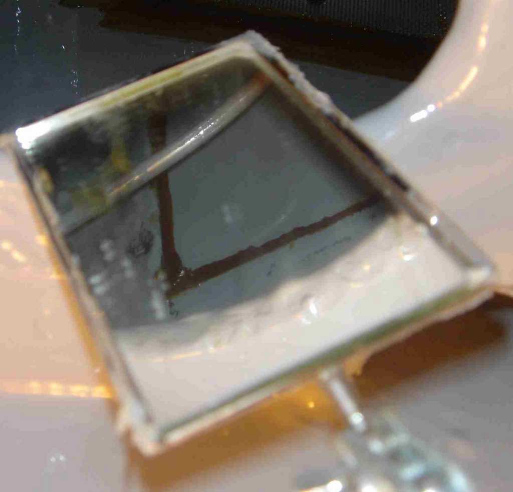
You can see in the inspection mirror that there's a beautifully perfect bead of flox running arount the perimiter of the lid. Two more to do then it's leak test time.


Saturday, November 05, 2005

Altitude Hold


In this photo you can see just barely see the pitch servo below the large black battery. to the left of the battery, you can see the control unit. Our altitude hold system is the Treo Avionics http://www.trioavionics.com/ The installation is fairly simple, first you locate the four components. The first is the Pitch servo. I located it directly behind the instrument panel and a short control arm will attach it to the elevator control horn.

Second, the two panel mounted components were installed in holes that we had cut out in the panel previously. We cut the holes originally based on dimensions from the trio web site. A small LCD and a rotary knob provide the interface to the altitude hold.


Then the 'brain' was installed. A small box that stands vertically, and must be oriented top-up and face the db connector forward. It was also mounted directly behind the instrument panel on the small shelf that we installed originally to hold the GRT AHRS boxes. (They didn't fit there). Now the shelf has the EFIS backup battery, the pitch servo, the altitude hold control box, the low voltage indicator/backup battery management module and the control relay for the backup battery. It is getting a bit crowded and I still have to find a place for the control rod for the manual gear extension.

After all of the boxes were mounted, I started in on the wiring. Locating the 4 conductor tefzel insulted shielded wire recommended by Trio isn't easy. I ended up calling Trio and bought 20' from them. If I had known it was so hard to find, I would have bought it at the same time as the altitude hold system.

I didn't like the solder on DB connectors that were provided. The rest of the aircraft is using high quality machined ($0.30/each) crimp pins provided by B&C (http://www.bandc.biz). I got some empty DB shells ready and started crimping pins and cutting wires. Each panel mount box gets a DB-9 and the controller uses a DB-25. The servo has a plastic molex style connector.

After it was all wired up, I ran a temporary power and ground wire to it to test before I strapped the whole bundle down into the aircraft. The LCD displayed 'System Test' endlessly. A re-inspection of the wires found that I had crossed two signal pins. After fixing that error, I powered it up and all worked fine. Configuration of the system will have to wait until I get the canard re-mounted and hook up the control arm.

I still need to fasten the bundle down, hook up the power wire to the panel mounted switch, run the permanent ground wire, run power to the switch, and hook up the control stick mounted disconnect button. Something to do on Monday...

Update

Coated lids of left tank with two coats of jefco, opened up right fuel tank, continued fabrication of rear seat console.

Friday, November 04, 2005

New builders log has arrived.

This site has been posted to make the builders log of N159BB available for all that wish to see. This will be the central place to check up on the latest progress, view photos, download files, and more.

Magneto Wires


I stopped by the hangar today to drop off some airplane parts and a paint sprayer that is to be loaned out. Had time to install the new magneto wires and remove the dessicant from the engine plugs. Was told that the dessicant is supposed to be blue when it is not 'used up' so it needed to be recharged. You can see it is pink in this photo. I removed the dessicant and took it home to recharge it in the oven at 275 for a while.

We had to remove the giant bendix magnetos because they don't clear the engine mount. A friend loaned us a slick magneto and we are using an electronic ignition on the other side. I recieved the magneto wires from Spruce. It is a custom set from Skytronics through Aircraft Spruce. I installed them tonight on the Magneto. I still need to clamp them down and run them properly.


Tuesday, November 01, 2005

Starters, probes and trays


Today I created a shim for the starter motor bracket. A friend had left some spare aluminum sheet to use so I figured it would be a good day to make the shim. The bracket we are using allows the mounting of a Toyota starter motor on the lycoming. However, the alignment of the pinion gear to the ring gear wasn't good and the ring gear was rubbing the starter shaft. I needed about a 1/16" extra clearance. A couple minutes on the bandsaw and the drill press and I had a shim which worked just fine. I used a transfer punch to line up the 4 bolt holes for the starter mount.


After I finished that I installed the bayonet mountings for the CHT probes. Cylinder #4 was a bit sticky, but the rest threaded right in. I installed the probes and temporarily tie-wrapped the wires to the back of the engine.

Thursday, October 27, 2005

Engine Lifting

I wrestled the engine crate up onto the engine hoist today. It took me a couple of hours to figure a way to get this 400lb crate up 5" onto the hoists legs. I wanted to be able to lift the engine in and out of the crate and still be able to store the engine resting in the crate. This also allows us to roll the engine around since the stand has wheels. I didn't want to leave the engine hanging on the stand because that is bad for the hydralic lift cylinder and the engine lift is borrowed.

After getting this thing lifted up and out of it's crate, Bill stopped by and we removed the magnetos and various other items that were in the way. We were able to test fit the engine mount and it looks good. Just one minor adjusment to make that isn't even related to engine clearance, rather I wasn't able to get one of the isolation cups into the mount because one of the upper tubes is too close to the cup. I'll have to have that tube adjusted.

Wednesday, October 26, 2005

GPS, Trim and EFIS

I mounted the GPS antenna in the nose today. It is mounted in the nosecone under a hatch. The fiberglass is transparent to radio waves so we can mount it down out of sight (and out of the airstream).

I also created a bracket for a Ray Allen position sensor to mount on the Strong pitch trim. I had to create a linkage to transfer the motion from the trim motor to the sensor and reduce the amount of travel. The sensor only has 1.2" of movement but the trim moves several inches. This took a lot longer than I expected.